Navigation Module - Mathematical Background
The following exposition will imply usage of the components selected for the Navigation Module of I.T.E.
Contents |
General Information
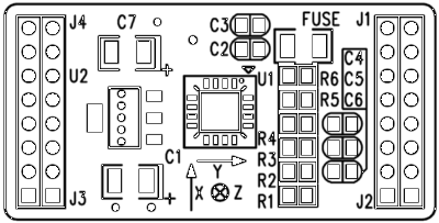
An accelerometer provides permanent supply of an up-to-date acceleration vector A<ax,ay,az>. This acceleration vector is aligned and located in the accelerometer’s coordinate system. Here is an extract from a specification (Figure 2 Top Part Layout, page 4, DC-SS009 ver. 2.0, User’s Guide, Sure Electronics).
When accelerometer is turned on, it reports the acceleration, which is “applied” to itself. In natural environment on Earth, there is always a Gravity, which causes a gravitational acceleration of -9.81 m/s2, always pointing to Earth core. If you imagine a working but still accelerometer, which is located in Ecuador, aligned so that X points to North pole, and Y is perpendicular to equator, and Z is pointing to ground, then the returned acceleration vector will be <0, 0, 1> in accelerometer native “g”-units, or <0, 0, 9.81> in m/s2 (in SI units). Former accelerometer has several modes (like precision divisor jumper), which extends its sensitivity with a cost of reducing sensing range. When a robot’s platform rotates (yaw, pitch or roll), the accelerometer rotates with the platform, since it is directly mounted on it. In this moment, the local coordinate system will rotate as relative to the world coordinate system (some point on Earth, which we will identify as axes origin). Due to rotation, accelerometer Z will no longer point to the center of Earth, and thus will not correlate with the gravity vector. Moreover, X and Y will still point to the robot’s front and right side, respectively, but for the distanced viewer, it will be obvious, that the robot has turned. If we will not take platform rotation into account, we will only be able to tell the distance, that robot made, but not its relative position in the world after move, nor its speed (since we don’t really know, where is the gravity vector is pointing to compensate it). We must always compensate (subtract) g-vector from the output vector, because, when a robot is standing on a solid ground, this acceleration will not cause a robot to move or change its speed. This coordinate system is identified as right handed. This means that the following matrices and rules will apply to transformed point. The result of applying transformation to original 3D column-vector V=[Vx,Vy,Vz]T, with affine rotation matrix R=Rx*Ry*Rz, where Rx,Ry,Rz – are corresponding rotation matrices for X,Y and Z axis, is a new column-vector V’=[Vx’,Vy’,Vz’] defined by the following rule:
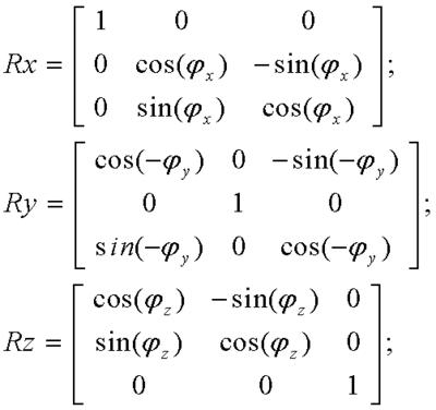
and the matrix R is defined as a product of matrices Rx,Ry,Rz, which are generally defined as follows:
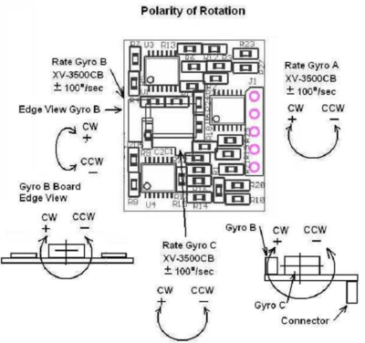
To be sure that everything will go smooth, we must verify the coordinate system of angular rate sensor (3D Gyro). As illustrated in the specification (page 6, RG 30 Three Axis Rate Gyro. Max angular rate: ±100 deg/sec. Technical Reference Manual, PCB rev 1.0) the positive rotation angle is clockwise, for each axis, as relate to the vector pointing towards viewer, which is fully corresponding to the rule of a left handed coordinate system. For the right-handed coordinate system, positive rotation direction must go counter-clockwise. This actually means, that a sign correction will be required there.
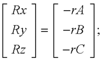
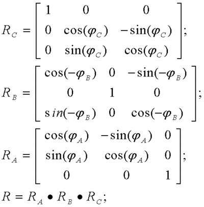
However, we must also notice, that axes of rotation for X and Z channel (named A and C in the datasheet) of the Gyro are swapped. So, in the final computational formula we will take this into account:
Computing the general rotation matrix R (note that we have swapped rotation matrices for channels A and C:
We compute the final generic rotation matrix using Matlab symbolic math:
>> syms rX
>> syms rY
>> syms rZ
>> Rx = [1 0 0; 0 cos(rZ) -sin(rZ); 0 sin(rZ) cos(rZ)]
Rx =
[ 1,      0,       0]
[ 0, cos(rZ), -sin(rZ)]
[ 0, sin(rZ),  cos(rZ)]
>> Ry=[cos(-rY) 0 -sin(-rY); 0 1 0; sin(-rY) 0 cos(-rY)]
Ry =
[  cos(rY), 0, sin(rY)]
[       0, 1,      0]
[ -sin(rY), 0, cos(rY)]
>> Rz=[cos(rX) -sin(rX) 0; sin(rX) cos(rX) 0; 0 0 1]
Rz =
[ cos(rX), -sin(rX), 0]
[ sin(rX),  cos(rX), 0]
[      0,       0, 1]
>> R=Rz*Ry*Rx
R =
[ cos(rX)*cos(rY), cos(rX)*sin(rY)*sin(rZ) - cos(rZ)*sin(rX), sin(rX)*sin(rZ) + cos(rX)*cos(rZ)*sin(rY)]
[ cos(rY)*sin(rX), cos(rX)*cos(rZ) + sin(rX)*sin(rY)*sin(rZ), cos(rZ)*sin(rX)*sin(rY) - cos(rX)*sin(rZ)]
[       -sin(rY),                        cos(rY)*sin(rZ),                        cos(rY)*cos(rZ)]
Algorithm
Using this result, let’s just write out the final algorithm:
- retrieve actual acceleration vector from accelerometer <ax,ay,az> in SI units
- retrieve actual rotation vector from gyroscope: <A,B,C> in radians for each output channel
- retrieve aligned rotation vector <rx,ry,rz>=<-C,-B,-A>
- create rotation matrix R from rotation angles in vector <rx,ry,rz>
- сompute matrix-vector product: <Ax,Ay,Az>T=R(<rx,ry,rz>)*<ax,ay,az>T.
Implementation
The following C code implements the above algorithm :
/*
	The following code illustrates transformations in the article on:
		wiki.endrobene.org
		info at endrobene.org

	copyright (c) 2011, fluxrobotics

	Transformations are applied according to the Right Handed Coordinate System.
	All units are SI (meter-kilogram-second-radian).
*/
#include "stdio.h"
#include "math.h"

typedef struct Vec3
{
	float x,y,z;
} Vec3;

typedef struct Mat3
{
	float m11,m12,m13;
	float m21,m22,m23;
	float m31,m32,m33;
} Mat3;

// Returned units in SI
bool readAccelerometer(Vec3 *retVecAccel)
{
	retVecAccel->x = 1; // your values here - m/s^2
	retVecAccel->y = 0;
	retVecAccel->z = 0;
	return true;
};

// Returned units in Radians
bool readGyro(Vec3 *retVecGyroAngle) // I've failed here, sorry. (я тут напартачил, прости)
{
	retVecGyroAngle->x = 0; // your values here - radians. They are the rotation angles of the platform.
	retVecGyroAngle->y = 0;
	retVecGyroAngle->z = 0;
	return true;
};

// Left multiplication of Matrix and Vector-column. result = mat*vec
void xMatMulVec(Mat3 *mat,Vec3 *vec,Vec3 *resultVec)
{
	resultVec->x = mat->m11*vec->x + mat->m12*vec->y + mat->m13*vec->z;
	resultVec->y = mat->m21*vec->x + mat->m22*vec->y + mat->m23*vec->z;
	resultVec->z = mat->m31*vec->x + mat->m32*vec->y + mat->m33*vec->z;
}

// Fills the matrix of rotation, based on input Rotation vector R = <rx,ry,rz>
void xMatFromRotation(Vec3 *vecR,Mat3 *mat)
{
	float cosX,sinX;
	float cosY,sinY;
	float cosZ,sinZ;

	sinX = sinf(vecR->x);
	cosX = cosf(vecR->x);

	sinY = sinf(vecR->y);
	cosY = cosf(vecR->y);

	sinZ = sinf(vecR->z);
	cosZ = cosf(vecR->z);

	mat->m11 = cosX*cosY;
	mat->m12 = cosX*sinY*sinZ - cosZ*sinX;
	mat->m13 = sinX*sinZ + cosX*cosZ*sinY;

	mat->m21 = cosY*sinX;
	mat->m22 = cosX*cosZ + sinX*sinY*sinZ;
	mat->m23 = cosZ*sinX*sinY - cosX*sinZ;

	mat->m31 = -sinY;
	mat->m32 = cosY*sinZ;
	mat->m33 = cosY*cosZ;
}

int main(int argc, char* argv[])
{
	std::printf("Test gyro rotation\n");

	Vec3 vecAcceleration_LCS; // Acceleration in Local coordinate system
	Vec3 vecAcceleration_WCS; // Acceleration in World coordinate system
	Vec3 vecGyro; // initial rotation vector from gyro
	Vec3 vecRotation;
	Mat3 matR;

	// Read devices
	readAccelerometer(&vecAcceleration_LCS); // Step 1
	readGyro(&vecGyro); // Step 2

	// Step 3
	// Transform Gyro rotation vector into basis of Accelerometer
	vecRotation.x = -vecGyro.x;
	vecRotation.y = -vecGyro.y;
	vecRotation.z = -vecGyro.z;

	// Step 4
	// Create Rotation matrix
	xMatFromRotation(&vecRotation,&matR);

	// Step 5
	// Move local coordinate system acceleration into world basis
	xMatMulVec(&matR,&vecAcceleration_LCS,&vecAcceleration_WCS);

	// Output values to user
	printf("Acceleration (Local basis - sensor):  <%5.3f,%5.3f,%5.3f>\n",
		vecAcceleration_LCS.x,vecAcceleration_LCS.y,vecAcceleration_LCS.z);
	printf("Rotation angles (radians):            <%5.3f,%5.3f,%5.3f>\n",
		vecRotation.x,vecRotation.y,vecRotation.z);

	printf("Acceleration (World basis - Earth):   <%5.3f,%5.3f,%5.3f>\n",
		vecAcceleration_WCS.x,vecAcceleration_WCS.y,vecAcceleration_WCS.z);
}
Computing required physical values
- 1) Computing speed in discrete time
- V<x,y,z>[i] = V<x,y,z>[i-1] + A<x,y,z>[i] × (t[i] - t[i-1]);
- where:
- V[i] - current velocity vector in world coordinate system, [m/s];
- A[i] - current acceleration vector, in world coordinate system, [m/s2];
- t[i] - current time value. Microseconds precision recommended, [s];
- V[i-1], A[i-1], t[i-1] - previous values from the respective stages. Initial values: V = <0,0,0>; A = <0,0,0>; t = current time;
- 2) Computing radius-vector in discrete time
- S<x,y,z>[i] = S<x,y,z>[i-1] + V<x,y,z>[i] × (t[i] - t[i-1]);
- where:
- S[i] - current radius-vector, in world coordinate system, [m];
- V[i] - current velocity vector in world coordinate system, [m/s];
- t[i] - current time value. Microseconds precision recommended, [s];
- S[i-1], V[i-1], t[i-1] - previous values from the respective stages. Initial values: S = <0,0,0>; V = <0,0,0>; t = current time;
World coordinate system origins at the robot start point. Initial world axes are aligned in respect to a robot's start position and orientation, except for Z which is pointing to the ground (Earth core, or, to be precise, Earth gravity center, which is slightly biased from the planet center).
Determine ground direction
Ground vector can be determined at start up. In steady state, the rotated ground vector of magnitude equal to g will be reported as an output. Required corrections can be applied.
<to be continued>
copyright © 2011, fluxrobotics 25 October 2011
