Optical encoding disks
The allowed diameter of encoding disc is 30 to 31 mm. The disk 30mm is a preferred size, but 31 mm can still be used, since the internal diameter of the encoder box is 32mm, there is still 0.5mm clearance. Special disk drawing application computes and draws prepared bitmap of disk with selected output resolution from the input specification.
Contents |
General information
The optical resolution of encoder depends much on the aperture size of the optical interrupter (sensor). There are three possible models, that can be used in our schematic (they are all from single series):
- Sensor type#1: TCST1103 (1.00mm aperture, 0.6mm minimal detectable resolution, 0.8-1.0mm preferred shutter line width*)
- Sensor type#2: TCST1202 (0.50mm aperture, 0.4mm minimal detectable resolution, 0.45-0.6mm preferred shutter line width*)
- Sensor type#3: TCST1300 (0.25mm aperture, 0.2mm minimal detectable resolution, 0.30-0.4mm preferred shutter line width*)
The minimal detectable resolution is based on estimation of shutter changing current between 10% and 90%.
Preferred line size is one that is chosen in our application as appropriate by taking into account sensor positioning precision.
Below is the estimation of the resulting count of lines on the inner and outer tracks for each type of the sensor (the encoding disk diameter is 31mm, the length of the line is 3.5mm):
- Sensor type#1: Ext = 94 / Inner = 66 (0.8mm wide line)
- Sensor type#2: Ext = 166 / Inner = 118 (0.45mm wide line)
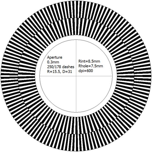
- Sensor type#3: Ext = 250 / Inner = 178 (0.30mm wide line)
- Theoretical maximum for sensor type#3: Ext = 376 / Inner = 266 (0.20mm wide shutter line)
The sensor type #3 gives the best resolution. When it is used with it preferred shutter line width there is 178 dashes on the inner side, which gives 178*2=356 pulses per revolution (transient up - black to white, and transient down - white to black), which results in angular resolution equal to 1.011°. This number can be rounded to be equal 1.0000° to alleviate accounting. The direction/count sensor is located on the inner side.
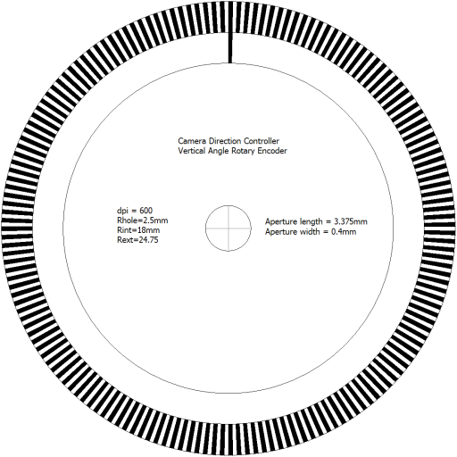
Example of encoding disk scanned by above mentioned sensors and used in motion control loop and wheel directing. It is presented just for illustration, because external track should contain only one black dash. This image then printed with the laser printer on the film, cut outside and drilled (or cut inside), then mounted to the coupling and assembled with encoders to morph optical position sensor:
The black&white image of the encoding disk is an output of specially written Encoder application (it is very raw yet). Manually labeled with specification text.

