File list
From endrobene wiki :: ITE
This special page shows all uploaded files. By default the last uploaded files are shown at top of the list. A click on a column header changes the sorting.
| Thumbnail | Name | User | Size | Description | Versions | |
|---|---|---|---|---|---|---|
 | 20:44, 24 February 2018 | Flag free ca en.png (file) | Executor | 377 B | (Canada flag free icon from https:// www. iconfinder. com/icons/92010/canada_student_icon#size=64) | 1 |
 | 03:15, 25 August 2016 | EmbComp-HW-PCIS8-photo2.jpg (file) | Executor | 75 KB | 1 | |
 | 03:13, 25 August 2016 | EmbComp-HW-PCIS8-photo1.jpg (file) | Executor | 110 KB | 1 | |
| 17:37, 23 August 2016 | HOA0901-11 appnote.pdf (file) | Executor | 119 KB | (application note for HOA0901-11 sensor (Honeywell)) | 1 | |
| 17:35, 23 August 2016 | HOA0901-11.pdf (file) | Executor | 365 KB | (official datasheet for HOA0901-11) | 1 | |
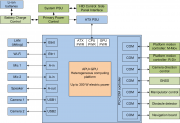 | 23:05, 27 May 2015 | Design-toplevel-component-connection.png (file) | Executor | 89 KB | (design schematic. Light green - modules planned or in production. Green - stable version of the module ready. Blue - 3-rd party component.) | 1 |
 | 01:34, 20 February 2015 | SidePanelInterface-Design-v1.png (file) | Executor | 35 KB | (The design of a functional interface of a Side Panel Interface board.) | 1 |
 | 00:11, 13 September 2013 | Entics-logo.png (file) | Executor | 12 KB | (Enchanted Robotics workshop logo. Public domain picture.) | 1 |
 | 22:07, 22 March 2013 | Stripped warning lines.jpg (file) | Executor | 464 KB | ("Warning lines" for "Under construction notice" template. I, the author, Oleh Kosan, declare this my own work as a Public domain image.) | 1 |
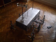 | 22:42, 8 March 2013 | ITE-photo-14june2012.jpg (file) | Executor | 187 KB | (Final version of robot in 2012. Complete on 14 June 2012. For Io with love.) | 1 |
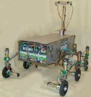 | 22:36, 8 March 2013 | Photo-ITE-assembled-May.jpg (file) | Executor | 231 KB | (Complete robot - ITE Photo. ~ approx May 2012) | 1 |
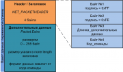 | 23:24, 9 June 2012 | Ru-Devices-Protocol-Header-UART.png (file) | Executor | 23 KB | (Protocol version 1.0. UART.) | 1 |
 | 23:19, 25 May 2012 | Flag free ukraine.png (file) | Executor | 737 B | (Flag_free_ukraine.png (Free icon from: http://icondrawer.com/free.php Ukraine icon)) | 1 |
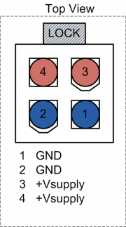 | 01:46, 7 May 2012 | Connector-MOLEX4-pinout.png (file) | Executor | 13 KB | (Molex 4-pin power connector (Single rail). Top view pinout.) | 1 |
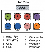 | 01:45, 7 May 2012 | Connector-MOLEX8-pinout.png (file) | Executor | 25 KB | (Molex 8-pin power connector (Battery). Top view pinout.) | 1 |
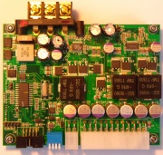 | 18:35, 4 May 2012 | M4-ATX-Device-Photo.jpg (file) | Executor | 1.2 MB | (A photo of M4-ATX Power Supply. This photo is released to Public Domain.) | 1 |
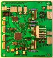 | 22:38, 3 May 2012 | CDC-Device-Photo-v5.jpg (file) | Executor | 1.21 MB | (Soldered CDC PCB. Version 5.7.) | 1 |
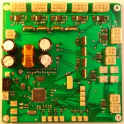 | 13:27, 3 May 2012 | PrimaryPowerController2-Device.jpg (file) | Executor | 1.11 MB | (PPC version 2.5 (2.6). Top side. Device photo. Soldered. Tested.) | 1 |
 | 20:15, 29 April 2012 | SidePanelInterface-Device-Photo-v1.jpg (file) | Executor | 505 KB | (Side Panel Interface. Version 1.0) | 1 |
 | 17:07, 17 April 2012 | Camera rotary encoder pitch.png (file) | Executor | 69 KB | (Fixed board dimensions. Encoding disk dimensions added.) | 3 |
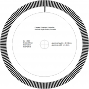 | 08:17, 15 April 2012 | Optical-Encoding-Disk-CDC-Vert.png (file) | Executor | 42 KB | (Vertical encoding disk version 1 (first working version)) | 1 |
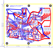 | 01:28, 12 April 2012 | CDC-PCB-v4.93.png (file) | Executor | 832 KB | (v. 4.93 (produced)) | 1 |
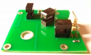 | 03:01, 10 April 2012 | Optic-Encoder-Camera-Vertical-Device-Photo.jpg (file) | Executor | 320 KB | (Optical encoder board for Camera vertical pan angle sensing. Version 1.0. Soldered sensors S1+S3 = TCST1300 (0.25mm), S2 = TCST1202 (0.5mm)) | 1 |
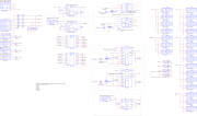 | 20:39, 7 April 2012 | PSU-Capture-v2.png (file) | Executor | 100 KB | (Version 2.91) | 3 |
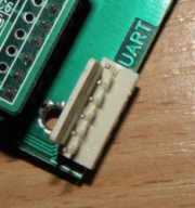 | 15:21, 5 April 2012 | Navi-DataConnector-Photo.jpg (file) | Swinemaker | 33 KB | (NAVI module UART connector) | 1 |
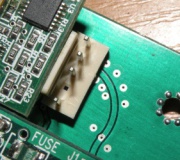 | 15:19, 5 April 2012 | Navi-PowerConnector-Photo.jpg (file) | Swinemaker | 45 KB | (NAVI module power connector) | 1 |
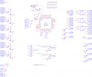 | 21:40, 1 April 2012 | PrimaryPowerController2-Capture.png (file) | Executor | 142 KB | (Version 2.5) | 1 |
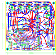 | 21:28, 1 April 2012 | PrimaryPowerController2-PCB.png (file) | Executor | 807 KB | (Version 2.5) | 1 |
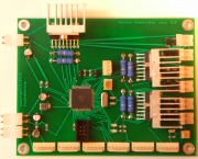 | 17:28, 30 March 2012 | PMC-Device-Photo-v5.jpg (file) | Executor | 743 KB | (Platform Motion Controller version 5 (PCB revision 2.2)) | 1 |
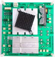 | 15:45, 25 March 2012 | PSU-Device-Photo-v2.jpg (file) | Executor | 621 KB | (PCB revision 2.7. 3.3V supply failed to start.) | 1 |
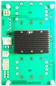 | 15:32, 25 March 2012 | AUXPSU-Device-Photo.jpg (file) | Executor | 353 KB | (PCB revision 2.7) | 1 |
 | 14:44, 25 March 2012 | XRS-TTL-Device-Photo.jpg (file) | Executor | 242 KB | (XRS-TTL. Large. 3xRS-232 to TTL.) | 1 |
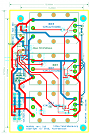 | 21:41, 24 March 2012 | AUXPSU-PCB.png (file) | Executor | 271 KB | (Revision 2.8 (errors fixed)) | 2 |
 | 21:32, 24 March 2012 | AUXPSU-Capture-Sch-V1.png (file) | Executor | 60 KB | (Fixed errors. Version 2.9) | 3 |
 | 19:41, 12 March 2012 | SidePanelInterface-PCB-v1.png (file) | Executor | 265 KB | (A two-sided PCB layout of the Side Panel Interface (ver. 1) with component names.) | 1 |
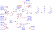 | 19:41, 12 March 2012 | SidePanelInterface-Capture-v1.png (file) | Executor | 51 KB | (Schematic capture of the Side Panel Interface (ver. 1)) | 1 |
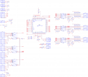 | 05:47, 11 March 2012 | PMC-Capture-v5.png (file) | Executor | 92 KB | (Schematic capture of the platform Motion controller.) | 1 |
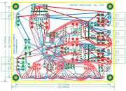 | 19:57, 10 March 2012 | PMC-PCB-v5.png (file) | Executor | 624 KB | (Platform motion controller PCB (version 5, revision 2.2) - 6 channels, ATMega64, no copper fill.) | 1 |
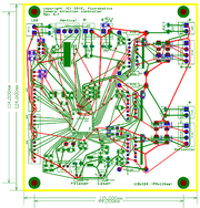 | 08:49, 10 March 2012 | CDC-PCB-v5.png (file) | Executor | 591 KB | (Minor PCB fixes (connectors renamed)) | 2 |
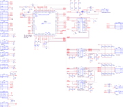 | 01:03, 10 March 2012 | CDC-Capture-v5.png (file) | Executor | 91 KB | (Capture of the CDC rev. 5.7) | 1 |
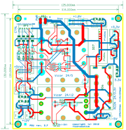 | 04:32, 1 March 2012 | PSU-PCB-V2.png (file) | Executor | 349 KB | (Two-sided PCB of the PSU. This is not a copper-poured version.) | 1 |
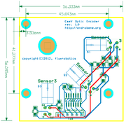 | 11:45, 28 February 2012 | Optic-Encoder-Camera-Vertical-PCB.png (file) | Executor | 87 KB | (Optical encoder board for vertical camera positioning. PCB with four mounting holes and three sensors (Type CamV) and with buffering IC (74HC14).) | 1 |
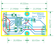 | 11:43, 28 February 2012 | Optic-Encoder-Large-PCB.png (file) | Executor | 63 KB | (Optical encoder board. Large PCB (Type 1), with buffering IC (74HC14).) | 1 |
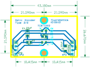 | 11:41, 28 February 2012 | Optic-Encoder-Small-PCB.png (file) | Executor | 49 KB | (Optical encoder board. Small sensor PCB (Type 2), without buffering.) | 1 |
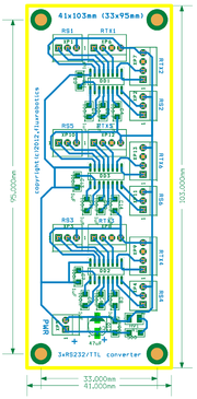 | 10:07, 28 February 2012 | XRS-TTL-PCB.png (file) | Executor | 137 KB | (PCB of the six-channel RS-232/TTL converter. Single-sided. Four mounting holes.) | 1 |
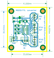 | 04:50, 28 February 2012 | RS232-to-TTL-PCB.png (file) | Executor | 72 KB | (New version PCB of the two-channel RS-232 to TTL converter. Single-sided version.) | 1 |
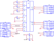 | 03:46, 28 February 2012 | RS232-to-TTL-Capture.png (file) | Executor | 51 KB | (Fixed version of RS-232 to TTL. This is a converter based on one IC (ST232 or MAX232) and only two inputs/outputs. There are also other schematics with more converters on single PCB.) | 2 |
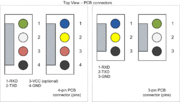 | 22:11, 27 February 2012 | Connectors-RTX-pinout.png (file) | Executor | 53 KB | (Corrected pinout. Black wire (GND) is always last.) | 2 |
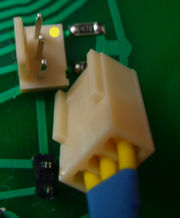 | 05:29, 27 February 2012 | Connector-Power-100T.jpg (file) | Executor | 187 KB | (3pin 0.100" (2.54mm) pitch connector. Yellow marks first pin.) | 1 |
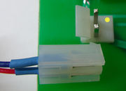 | 05:28, 27 February 2012 | Connector-Power-156T.jpg (file) | Executor | 153 KB | (3pin 0.156" (3.96mm) pitch connector. Yellow marks first pin.) | 1 |
 First page |
 Previous page |
 Next page |
 Last page |