TTL-to-RS-232 converter
Contents |
This module provides logic-level signal conversion to RS-232 levels and vice versa. Such level conversion is required, when interfacing, for example, an ATMega8 uC via UART with Computer COM port.
This separate board allows not to place converting IC to the main board. User must ensure that output TTL cable length is no more than 20-25 cm (less than 10 cm is better).
Schematics
Below is a schematic capture of the board

PCB
Single sided PCB is shown below:

Single sided PCB but for six channels:

PCB mask for TSSOP version
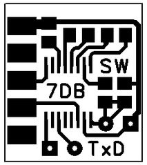
B&W PCB mask for compact RS-232 to TTL converter
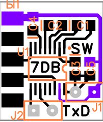
Component layout


Notice GND traces and pads are shown in purple color.
J1 connector - 5V power for the converter;
J2 connector - TxD/RxD signal line. RxD pin is marked as circle and positioned near the "TxD" caption.
Wiring
The pitch of the connector is 0.100". Connector footprints in OrCad are:
- POLCON.100/VH/TM1SQS/W.300/3 - for the 3-pin connector
- POLCON.100/VH/TM1SQS/W.300/4 - for the 4-pin connector
3 pin connector for RS-232 signal
- Pin#1 - RXD - Green/Blue
- Pin#2 - TXD - White/Yellow
- Pin#3 - GND - Black
4 pin connector for TTL-COM signal
- Pin#1 - RXD - Green/Blue
- Pin#2 - TXD - White/Yellow
- Pin#3 - VCC - Red / May be not connected
- Pin#4 - GND - Black

Device photo
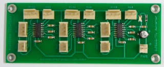
A photo of the assembled XRS-TTL. The board can be further compacted.
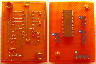
Photo of both sides of produced boards. (PDIP)
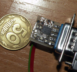
Photo of compact board version (TSSOP).


Notice blue and yellow markers which indicates first pin.