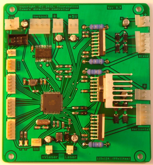
Camera Direction Controller
Camera direction controller - is an electronic microcontroller-based board used to control a stereo camera tower pitch/yaw (look-at direction). Based on ATMEL ATMega64A-16 @ 14.7456 MHz. Adaptive control of stepper motors. Position feedback angle sensed by incremental rotary encoder with index and zero tracks is returned to control logic for dynamic compensation.

Contents |
Actuators
Bipolar stepper motors (5-12V).
- Motor 1 - pitch control. Model MP35EA. Geared. (12V, 92mA, 4-Phase bipolar, gear ratio 1:85, step angle = 7.5 deg, torque = 0.4 kg*cm = 39.2 mN*m = 5.6 oz-in). (Specification page: http://www.mmc.co.jp/mmcg/cmi/en/01030403.html)
- Motor 3 - yaw control. Model ALTN1728D63. Nema 17. OSM Technology. Dual shaft version. (1.8 deg step angle, step accuracy = 5%, rotor inertia = 82 g*cm2. Dielectric strength = 500VAC. Weight = 0.4 Kg). Holding torque (2 phases on) = 0.59 N*m, Rated current = 2.0 Amps DC. Phase resistance = 1.4Ohm +- 10%. Rated voltage = 2.8 VDC. Phase inductance (typical) @ 1KHz = 2.7 mH +- 20%. Connector: L1 = Black + Green, L2 = Red+Blue.
Sensors
Optical interrupter VISHAY TCST1202 (preferred) (0.5 mm aperture) or equivalent with higher or lower resolution (TCST1103 - 1.0 mm, TCST1202 - 0.5 mm, TCST1300 - 0.25 mm).
Current sensor is 1.0 Ohm shunt resistors for each coil of motors #2 and #3.
Sensor groups
- CamV (Camera Vertical Encoder). Sensor connector #2.
- S1, S3 - quadrature [A,B]
- S2 - zero track
- CamH (Camera Horizontal Encoder). Sensor Connector #3.
- [S2, S1] - quadrature [A,B]
- S3 - zero track
Vision system
Two Philips spc 2050nc web cameras.
- 6 FPS @ 1600x1200, 90 FPS @ 640x480
- low noise
- good image quality at low illumination
- (!) sometimes programmatically set focus is lost/stuck due to vibration
Version 6
This version is planned for development.
Schematic capture
PCB Layout
Device photo
Version 5
This version is 50% smaller and also fixes most flaws in a revision 4.x.
Schematic capture
PCB Layout
Device photo
Test results
Flaws
- Design:
- Current sense is too noisy
- Extra motor rail #2 is redundant
- Current sense is too much resistance for stepper motors, use smaller sense resistors with dedicated amplification and noise-cancellation.
- Consider using turn failure detection for overloaded motor.
- Enable reading of how much motor has rotated with motor feedback data.
- Do not use L298DD for vertical axis as it overheats too much in long use.
- Consider changing vertical axis motor (and requirements) to something at least 2x-3x more powerful (mechanical resistance of hanging wires is too high in some situations)
- Weak (and high ESR) capacitors (currently C11) on Vs rail of CamH motor drivers (DD4, DD5) results in voltage drops and bursty CamH motor operation during fast turns (when Vs3 = 5 V). Temporary fix of 100uF 25V low ESR electrolytic capacitor applied.
- Board operates at lower than max frequency, which limits response time. Consider replacing BQ1 from 14.7456 MHz to 16 (or overclock to 20 MHz).
- Implementation:
- Laser connector is very low quality, it does not hold very well and lock is unreliable.
- Do not use 2-pin connectors for signal/low power anymore.
- All plastic locks of 2-4 pin power connectors should be oriented not towards capacitors, especially tall (SMD) capacitors, which easily tear away.
- Do not use SMD-polymer capacitors, use through-hole polymer capacitors instead.
Firmware binding
- Optic interfaces:
- XP2 - FW: "Sensor1" - function "Brake" - disabled by ENABLE_SENSOR_1 in "CDC ver. 5.0" firmware.
- XP4 - FW: "Sensor2" - function "CamV" - vertical axis drive. Zero position is 27 ticks away.
- XP6 - FW: "Sensor3" - function "CamH" - horizontal axis drive.
Version 4
This board is able to control three stepper motors and laser. Capabilities: stepper motor micro-step control, current sense and encoder feedback, laser control. This schematics has some minor design flaws, which will be fixed in future release. However, it performs well all tasks for which it is was designed.
Schematic capture
PCB Layout
Device photo
Version 3
Was not produced, because of missing brake and laser control, and Yaw motor model change to higher-current.


