Platform Motion Controller
Platform motion controller - is an electronic microcontroller-based board which task is a smooth, fast and energy efficient control of the wheel driving and rotating motors. It is based on the ATMEL ATMega64A-16 @ 14.7456 MHz µC, however, since a single board controls a bunch of motors simultaneously (using a software emulated adaptive PID control) the solution is highly demanding on floating point computational power, which may lead to changing µC from ATMega series to ARM7 (e.g. NXP LPC2103) in the future revisions.
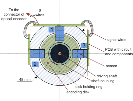
Position feedback angle, read by incremental rotary encoder with index/dir and zero tracks, is returned to control logic for dynamic regulation.
Contents |
Actuators
Geared DC motors TRW Globe IM-15 series, model 409A6024. Six units for rotation plus six units for wheel drive.
- → Motor DC short stack, 24 VDC, 5200 rpm (±10%), current @ no load = 0.14 A, rated torque = 4.0 oz*in, current at rated torque = 6.00 oz*in/amps, resistance 9.0 Ohms.
- → Gearbox (gear ratio 1:100, torque multiplier 51.0, max continuous torque 178 oz*in = 0.128 kg*m).
- → Total length = 4.189 inches = 106.4 mm.
Total power: Max contiguous torque = 178 oz*in = 1.256 N*m = 12.81 Kg*cm. See oz·in→N·m, N·m→kg·cm
Sensors
- Optical interrupter VISHAY TCST1300 (0.25 mm aperture).
- Current sensor - shunt resistive voltage drop estimated with ADC
All optical sensors are mounted on a PCB in a sensor placeholder where the encoding disk is also located.
Sensor groups
- Drive/Motion (Drives the wheel). Sensor connector #2.
- S1, S2 - quadrature [A,B]
- Rotation/Direction (Rotates the wheel vertical axis). Sensor Connector #3.
- [S1, S2] - quadrature [A,B]
- S3 - zero track.
Version 5
Version 5 is planned for production. It is capable of driving six DC motors and use encoder output data to form a closed loop control. Two PMC boards are able to drive and direct wheels (12 motors total). Inter-board communication is available through the I2C interface. Board to system PC communication is performed with UART.
Schematic capture
PCB Layout
Two-sided PCB is shown below:
Device photo
Parts list
Test results
Flaws
- Design
- Unfiltered current feedback signal
- Too high driver IC resistance. Poor operation at high-frequency PWM. Consider using CMOS H-bridge instead.
- Poor uC performance, use STM32 instead.
- Too much compute resources spent on bit-banging DD1-DD3 Parallel-to-Serial shift registers (optic data). Use direct sensor connection (with CMOS/LevelShift buffers).
- Sensor data transmission is unreliable through long wires.
- Too much wires coming from/to motors. Consider giving each motor individual servo controller with one high-level motion controller.
- Implementation
- Bug in XP1-XP3 placement. Connectors should stay within PCB border.
- SMD Capacitors (like C3) are poorly soldered. Through-hole capacitors should be used instead.
- Power wires are too long and high resistance (including wires from power connector XP2).
- Input power connector XP2 does not give high enough current capability. Use 4-pin molex instead.
Versions 4 and below
- Version 4 was designed for 12 DC motors with separated power and logic parts (was still too complex and too large for production).
- Version 3 was designed for 12 DC motors with unified power and logic parts (was too complex and very large). Used a lot of 74HC165 ICs to extend input signals.
- Version 2 was a prototype for 4 DC motors (L298), assembled on the prototype board. It used 74HC165 and 74HC595 to extend input and output pin count.
- Version 1 was a prototype version for a single low power DC motor (L293B Half-bridge IC). It used optical encoder's feedback data to control motor.
See also


